Monday, July 8, 2019
CADALYST - Free Stuff for CAD Users
Here is a link to CADALYST magazines "Fabulous Freebies for CAD Users - 2019"
Friday, June 28, 2019
Navisworks 2018 Database Link w/ Excel - Primer
The Process
In order to connect an external data source such as an Excel spreadsheet or an Access database to a Navisworks model, we need to configure a DataTools within Navisworks. We will then be configuring the database connection. When working with the DataTools in Navisworks, there are a few very important rules to keep in mind. If you are using a 32-bit workstation, then you need to utilize the 32-bit ODBC drivers. 64-bit workstations need to utilize 64-bit ODBC drivers. It is also important to note, that the link to Navisworks is one way. Data can be linked and viewed inside of Navisworks, but the data can’t be updated within Navisworks.
My workstations are all Windows 10 64-bit workstations. My PC’s are using Microsoft Office 365. My Mac running Windows 10 64-bit on parallels using Office 365. The MS Access 2013 runtime drivers can be downloaded here: https://www.microsoft.com/en-us/download/confirmation.aspx?id=39358 If you are using an older version of office the MS Access 2010 drivers can be downloaded from here: https://www.microsoft.com/en-us/download/details.aspx?id=13255.
Data Source Setup
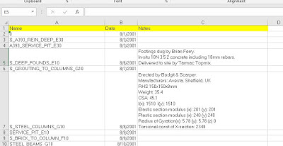
The Gatehouse project includes a sample Excel spreadsheet which is why I am using it as an example. The first thing I did to the file was add three column headers to identify the “Name”, “Date” and “Notes” columns (Figure 1). We are creating these labels to identify the columns.
 | |
|
Our next step, you need to have the ODBC drivers installed, otherwise you will not have the data connection option. With that done, open Navisworks and the Navisworks model that you want to connect your external data source to. In this example, I am going to open the gatehouse model as indicated above. In Navisworks, on the Home tab, Project panel, click on the File Options button (Figure 2). This will open the File Options dialog.
 |
| Figure 2 – Accessing the File Options |
In the File Options dialog, we will start the process of configure our database connection (Figure 3). As shown in Figure 1, click the DataTools tab and then click the New button to create a new DataTools link to open the New Link dialog.
 |
| Figure 3 - File Options dialog for creating a new DataTools link |
In the New Link dialog (Figure 4), we first want to name the new link connection we are creating. For this example, I am using the name “Gatehouse Example”. We then need to select the ODBC Driver Connection type. We are going to be working with a Microsoft Excel data source, so select the “Microsoft Excel Driver (*.xls, *.xlsx, )” driver. Then click the Setup button to open the ODBC Microsoft Excel Setup dialog.
 |
| Figure 4 - New Database Connection Link dialog |
After you have selected your excel file, click OK to close the ODBC Microsoft Excel Setup dialog.
If you are having issues with your Database Link connecting to Excel, be sure to check the Version of Excel database that you are using.
 |
| Figure 5 - ODBC Setup Dialog for Excel |
 |
| Figure 6 - Edit Link |
SQL String
The SQL string is used to specify how the database will be queried. I have found this part of configuring the database connection to be the most difficult. Fortunately, there are a lot of external resources available for creating SQL strings. My personal recommendation is to keep it as simple as possible.
The code that we will be creating for this example is:
SELECT * FROM [Gatehouse_Layerinfo$] WHERE "Name" = %prop("Item","Layer");
We start out our SQL String with SELECT * FROM The “*” is actually a field name, in this particular example, I am using the wildcard to query all the fields.
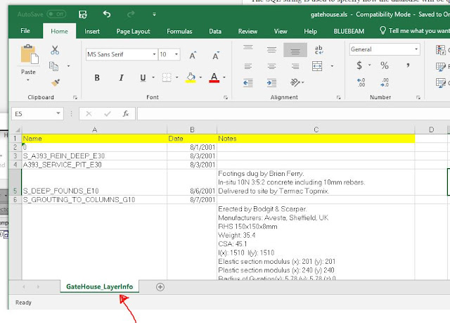
[Gatehouse_Layerinfo$] This is the Excel sheet tab name (Figure 7) that we want to query in our Excel spreadsheet. The Excel sheet tab name must be spelled just as it is in Excel and should be followed with the “$”.
 |
| Figure 7 |
WHERE "Name" = %prop("Item","Layer"); This is where we are going to define what data we are going to bring from the Excel spreadsheet into Navisworks. For our example, we are going to conditional match the value Layer property data for each element that can be found in the Item tab and match that with a value in the Name column of the Excel spreadsheet.
“Name” refers to column that we will be searching in the Excel file.
%prop is a SQL command that allow you to retrieve model data for conditional matching.
("Item","Layer"); “Item” refers to the Item tab in the Properties Window. “Layer” refers to the internal file property, in this example, the Layer (Figure 8).
 |
| Figure 8 – Navisworks Properties Window |
SELECT * FROM [Gatehouse_Layerinfo$] WHERE "Name" = %prop("Item","Layer");
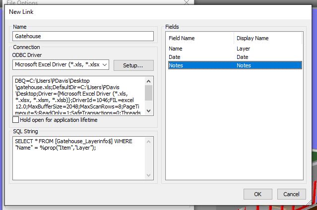
The next step in the process is to specify what information we are going to display in the Properties window. In the Field section of the Edit Link dialog (Figure 9), we are going to specify what Field names to list and the display name to use. Using Figure 9 as a reference, add the Field and Display Names.
Note that we are having the Field Name “Name” display as “Layer” in Navisworks. The Name column in our Excel spreadsheet refers to an AutoCAD Layer and rather than changing the column name in Excel, we can have Navisworks use a different Display Name.
 |
| Figure 9 - Inserting the Field and Display Names |
After you have entering the Field Names, click OK to close the Edit Link dialog box. Make sure that the “Gatehouse Example” DataTools Link that we just created is checked. This will enable it in our current session. Click OK to close the File Options dialog.
 |
| Figure 10 - DataTools |
 |
| Figure 11 - Foundation Selected with External Data Displayed |
If you have gotten this far and it is not working, a lot can go wrong. The first thing to check is the SQL String text. Then check to make sure that your using the correct version of Excel, which might be different than the selection, I made in Figure 5. Also, make sure that the Excel file you are trying to access in Navisworks is not open. That can cause issues as well.
This Gatehouse example is not the most robust example around, but it is a great starting point. Start with something simple so you can make sure that your database connection is working, before trying it on a more complicated project with a lot of data to query. As many of you are aware, CAD and BIM applications are not great data entry applications, so having this type of data linking capabilities is very beneficial.
Thursday, June 27, 2019
Navisworks - Multiple Iterations and Locked Files
While working in Navisworks and you find that you are updating your models frequently, you have probably ran into the issue of having to close your Navisworks model in order to update your appended model. There is a quick way to get around this.
In the Options Editor > Model > Performance, make sure “Close NWC/NWD Files on Load” is checked. This will now allow you to overwrite NWC files without unloading them in your NWF file. So when you have an updated NWC that has overwritten the existing file, you just need to refresh Navisworks for the new model(s) to load.
In the Options Editor > Model > Performance, make sure “Close NWC/NWD Files on Load” is checked. This will now allow you to overwrite NWC files without unloading them in your NWF file. So when you have an updated NWC that has overwritten the existing file, you just need to refresh Navisworks for the new model(s) to load.
Wednesday, June 26, 2019
Revit OpEd: Eccentricity of Wall Footing
Revit OpEd: Eccentricity of Wall Footing: I replied to a thread at AUGI regarding the Eccentricity parameter of a Wall Footing. They observed that Revit seemed to ignore their input ...
BIM/VDC Software Listing
Construction (Coordination)
- Autodesk Navisworks Manage
- Solibri Model Checker
- Tekla BIMSight
- BIM 360 Collaboration (Glue)
- 3D Repo
Construction (Other)
- Autodesk Navisworks Manage / Simulation (4D)
- Solibri Model Checker
- Vico Office Suite
- Bentley ConstrucSim (4D)
- Tekla BIMSight
Design - Architecture
- Autodesk Revit Architecture
- Graphisoft ArchiCAD
- Nemetschek Allplan Architecture
- Gehry Technologies - Digital Project Designer
- Nemetschek Vectorworks Architect
- Bentley Architecture
- 4MSA IDEA Architectural Design (IntelliCAD)
- CADSoft Envisioneer
- Softtech Spirit
- RhinoBIM
Design - Structure
- Autodesk Revit Structure
- Bentley Structural Modeler
- Bentley RAM, STAAD and ProSteel
- Tekla Structures
- CypeCAD
- Graytec Advance Design
- StructureSoft Metal Wood Framer
- Nemetschek Scia
- 4MSA Strad and Steel
- Autodesk Robot Structural Analysis
Design - MEP
- Autodesk Revit MEP
- Bentley Hevacomp Mechanical Designer
- 4MSA FineHVAC + FineLIFT + FineELEC + FineSANI
- Gehry Technologies - Digital Project MEP Systems Routing
- CADMEP (CADduct / CADmech)
Sustainability
- Autodesk Ecotect Analysis
- Autodesk Green Building Studio
- Graphisoft EcoDesigner
- IES Solutions Virtual Environment VE-Pro
- Bentley Tas Simulator
- Bentley Hevacomp
- DesignBuilder
Facility Management
- Bentley Facilities
- FM:Systems FM:Interact
- Vintocon ArchiFM (For ArchiCAD)
- Onuma System
- EcoDomus
Monday, January 28, 2019
Navisworks Redline Tools
I don't know if it is just me, but it does not seem like Autodesk is doing much development around Navisworks. One new feature I would really like to see added is a markup stamp. This would help accelerate markup sessions.
Anyone know of a 3rd party app that does this inside Navis?
Anyone know of a 3rd party app that does this inside Navis?
Monday, January 16, 2017
Schedule Pipe Fitting Angles
I am working on a project that is very complex in nature and has a result, has presented some very interesting opportunities. On the project, we are providing some general BIM/VDC Support Services. We are not modeling. One of the more interesting aspects of the project is the number of custom HVAC and Pipe Fittings in the project. This is probably a good Segway into discussing setting up your Revit MEP template, but today I just wanted to discuss how to report Fitting Angles. It's a two step process.
The first step is to create a shared parameter to capture the fitting angle. The second step is to modify all of your fitting families. In this case, I will work with Pipe Fittings.
Step 1
Step 2
The first step is to create a shared parameter to capture the fitting angle. The second step is to modify all of your fitting families. In this case, I will work with Pipe Fittings.
Step 1
- With either a Project or a Family open (it doesn't matter which), go to Manage tab » Shared Parameters.
- If you haven't created a Shared Parameter file yet, click 'Create...' and this will start a new file to act as a database for your Shared Parameters.
- Once created (or if already created), click 'New...' under Groups. You can name the Group "Pipe Fittings" or whatever you wish.
- Then click 'New...' under Parameters to create a new Shared Parameter. Name it "Angle (Scheduled)" or whatever you wish.
- Be sure to choose "Angle" from the 'Type of Parameter' drop-down menu. Click 'OK', and 'OK' again.
Step 2
- Open one of your Pipe Fitting Families for editing.
- Go to Family Types (the icon with the four blue squares on the left side of the ribbon) and click 'Add...' under Parameters.
- In the following dialog, set Parameter Type to "Shared parameter" and then click 'Select...' to choose which Shared Parameter to add.
- Select your parameter from the list and click 'OK'.
- Set this Parameter to "Instance" and then click 'OK'.
- Now, if the Formula field for this Shared Parameter, enter "Angle". Be alert, because the exact name of this parameter may vary.
- Click 'OK' and reload the Family back into your Project, overwriting the previous version.
Monday, December 19, 2016
BILT NA 2017 - Abstract Submission Reminder
Hey you! Yes, you! Remember back at school when you’d get caught
talking to someone during class, and we’d all have that one teacher who’d say,
“Got something to share with the class?” Well, BILT North America (formerly RTC NA)
is currently calling for abstracts and this is your time to shine!
Are you implementing new methods in your workplace that others
in your industry can benefit from? Maybe you’ve found an alternate method
that’s a more efficient way of modeling a project or it’s something else
altogether. If you’ve ticked any of these boxes, we encourage you to turn these
into abstracts and submit them for consideration in the BILT NA 2017 program.
On the other hand, if you haven’t ticked any of the boxes above,
fear not. If you have an idea that you think is worth submitting an abstract
for, but you’re not sure if it’s something that can make the cut for our
program, feel free to discuss this in confidence with our speaker manager,
Robert Bell. We’re always looking for ‘out of the box’ submissions.
The BILT NA Committee looks forward to receiving your abstract
submissions before Wednesday
January 4, 2017 11:59pm EST.
Kind Regards,
R. Robert Bell
Chairman, BILT North America
Sunday, October 30, 2016
Clearing Checking Results In Solibri Model Checker
JD Sherrill posted: "Why this is Important: There will be times when you may want to clear out all the results generated from a previous check and start with a fresh, unchecked model. Perhaps you have modified a ruleset and you would like to repeat a check using the new v"
|
Saturday, October 29, 2016
RTC Global News
|
Thursday, September 29, 2016
RTC Europe 2016 - Vision 20/20 Competition!
| ||||||||||||||||||||||||||||||||||||||||||||||||||||||||||||||
| ||||||||||||||||||||||||||||||||||||||||||||||||||||||||||||||
Subscribe to:
Comments (Atom)
Is anyone using Deep Space for analytics? https://www.deepspacesync.com/
-
If you are looking for information on how to perform a clean uninstall of Autodesk products, here is a link to a good article on the proces...
-
Systematic Model Review for Effective Coordination Early Registration Deadline: September 6, 201...


